¶ Introduction
The hold-down system is a passive device designed to keep the rocket secured to the launch rail until sufficient thrust is generated for a safe liftoff. It is based on a passive release mechanism based on a mechanical fuse, in which a calibrated pin breaks once the engine produces sufficient thrust for a safe liftoff.
¶ Applicable and Reference Documents
- 2025_C_ST_HOLD-DOWN_DJFSlinging hardware description
- DCD websiteMechanical fuse provider
¶ Requirements
- EuRoC-LV-RQT-1020All vehicles using at least one liquid propellant shall employ a hold-down system that will release the rocket only after sufficient thrust for stable flight is achieved
¶ Overview
The hold-down system is based on a COTS mechanical fuse component, which contains a pin designed to break at a defined tensile force. The device is mounted through the rocket boattail, fixed on one side to the thrust plate and on the other to a beam attached to the launch rail legs. It separates when the engine generates sufficient thrust, with the larger part remaining on the ground and the smaller head lifting off with the rocket. The pin is interchangeable, allowing different breaking force values to be selected depending on the use case. A tensioning device ensures preload in the system before launch, preventing shocks that would otherwise occur if the cable were untensioned. A schematic view of the system is shown below.
¶ Parts Description
¶ Mechanical Fuse
The core element of the system is the mechanical fuse containing an interchangeable pin. It is procured from the Canadian company DCD, with reference number 00570-202 and 00565-100 pins rated for a breaking force of 1000 [lb] (approximately 4.2 [kN]). Detailed calculations supporting the choice of pin are presented below. The fuse costs approximately $450, while the pins are about $50 per pack of five.
¶ Beam
The beam is clamped to both launch rail legs, extending around the rocket. The clamps primarily ensure contact with the rail but do not provide significant structural function, as the load is mainly directed upward and transmitted directly to the launch rail legs. The beam is manufactured from S355J2H steel, with dimensions of 60[mm]x60[mm] and a wall thickness of 8[mm]. Its length of 3[m] was arbitrarily chosen based on visual inspection of launch rail pictures, due to the unavailability of CAD models.
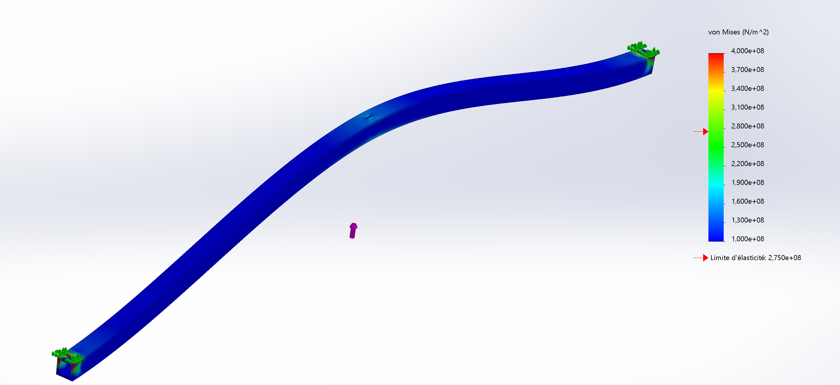
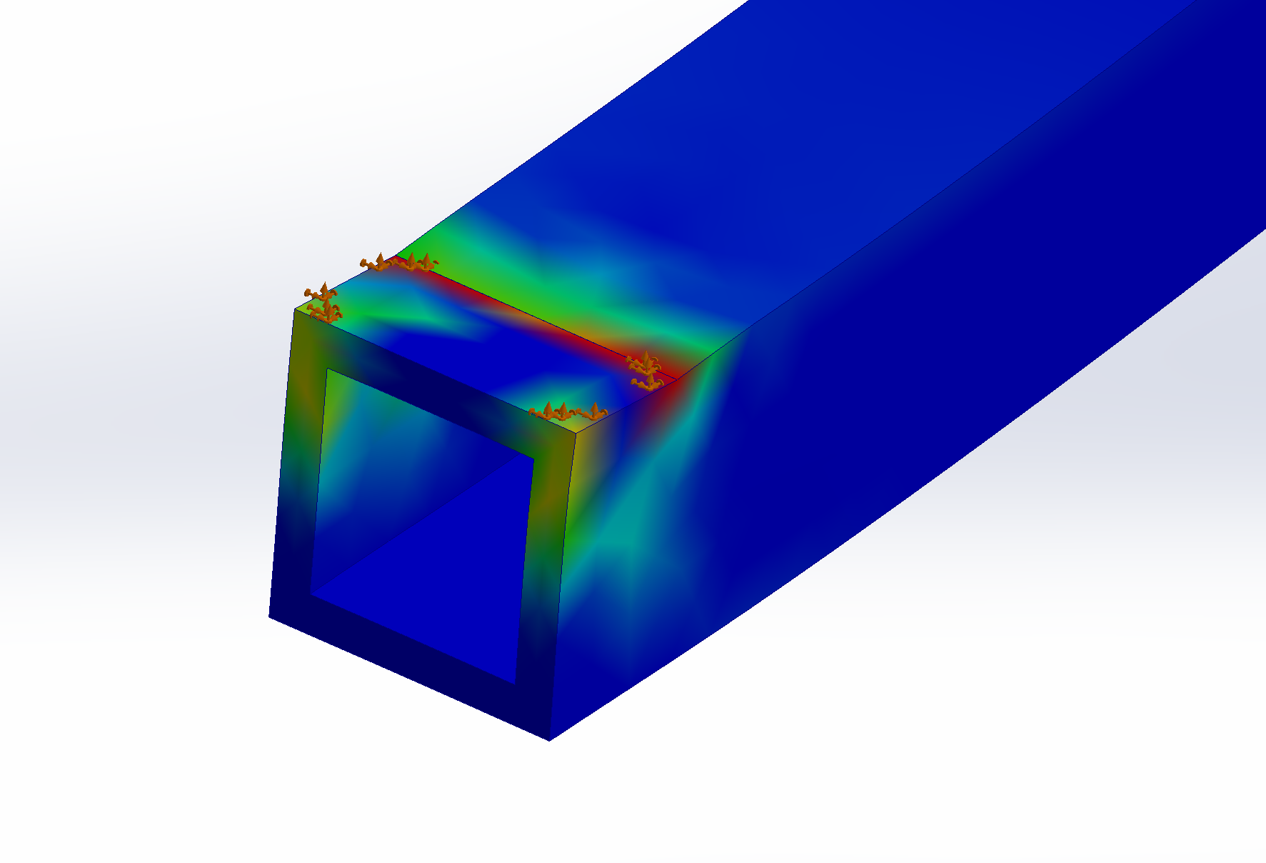
¶ Simulations
The beam was analyzed through static FEA simulations to verify that it could withstand the forces exerted by the rocket. Two rectangular areas corresponding to the beam–rail leg contact surfaces were defined as fixed supports, while the applied load was modeled as an upward force distributed over a circular area equivalent to the diameter of the bolt connecting the cable to the mechanical fuse. The simulation assume the worst-case scenario where the load is applied at the extremities of the beam, and uses a load of 10[kN] which is more than twice the pin breaking force. Appart from edge effect anomaly the result was deemed acceptable
¶ Pin
The selection of the pin breaking force followed the procedure detailed below.
¶ Minimum Thrust for Stable Flight
In order to satsify the given requirement, the first step was to determine what is the minimum required thrust to reach sufficient launch rail exit velocity for a stable flight. This is done by simply applying Newton's second law while Firehorn is still being guided by the launch rail.
The following assumptions can be made:
- constant mass during liftoff along rail
- because total time along rail is small
- constant engine thrust during liftoff along rail
- because startup transient occurs while rocket isn't yet released from hold-down
- constant angle between rail and gravity vector
- rail assumed rigid enough
- 1 dimensional motion of the center of mass
- rail buttons designed to restrict other degrees of freedom
- friction forces neglected
- friction losses small enough to be neglected / can be compensated for with margins
- rocket considered attached to rail along entire rail length
- aft rail button designed to restrict other degrees of freedom on its own, in reality the effective length will be slightly shorter
the following system of equations can be defined:
where is the length of the launch rail, is the acceleration of the rocket, is the time it takes the rocket to exit the rail, is the engine thrust, is the rocket wet mass, is the angle between the gravity vector and the launch rail and is the rocket rail exit velocity.
Solving this system of equation allows us to highlight the following relation between and :
which when plotted for and gives the following graph:
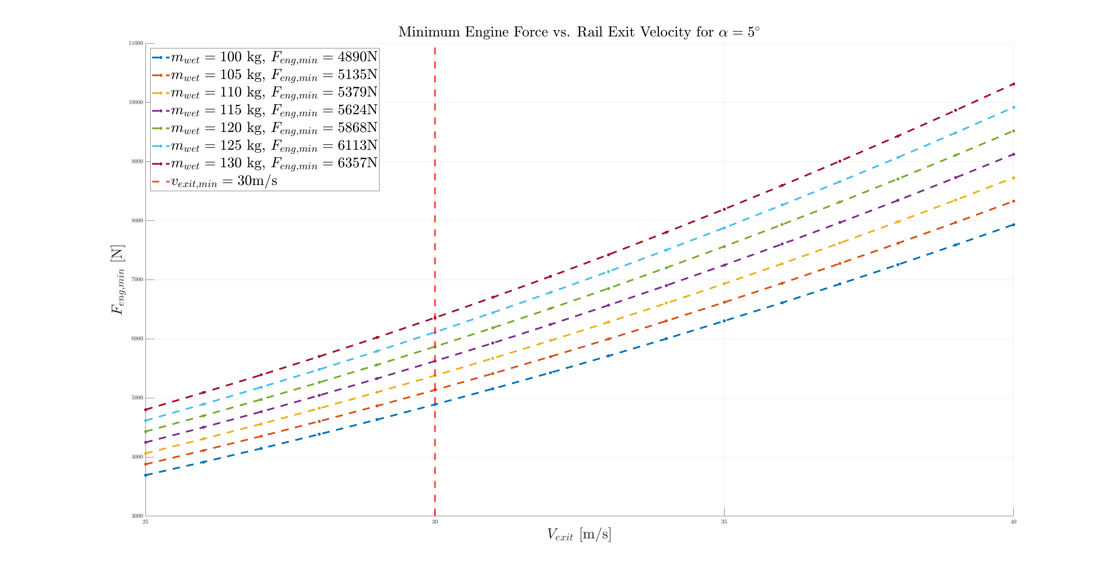
which allows us to determine the minimum required engine thrust to reach the target rail exit velocity of depending on the rocket wet mass .
¶ Force Balance on Hold-Down
Now that the target engine thrust has been established, the hold-down pin can be sized accordingly. To do this, a simple 2D force balance system can be written. The following assumptions can be made:
- constant mass during liftoff along rail
- because total time along rail is small
- constant engine thrust during liftoff along rail
- because startup transient occurs while rocket isn't yet released from hold-down
- no motion of the center of mass
- since the hold-down hasn't broken when it's exerting a force on the rocket, static analysis (no motion) can be used
- effects of engine transient neglected
- this assumption introduces the most error
- friction with rail modeled according to Coulomb's Law
With these assumptions, the following system of equations can be written:
where:
- is the friction force applied by the rail on the rocket
- is the friction coefficient between the rail and the rocket
- is the support force applied on the Retractable Rail Buttons in a direction perpendicular to the rail
- is the angle between the gravity vector and the launch rail
- is the engine thrust
- is the force applied by the Hold-down on the rocket to prevent it from moving
- is the angle between the force applied by the Hold-down pin and the rocket main axis
- and is the force due to the gravity

This system of equations can be solved to express , and as a function of the other parameters:
with the following simplification for readability: \lambda \coloneqq \frac{\sin(\alpha)+\mu\cos(\alpha)}
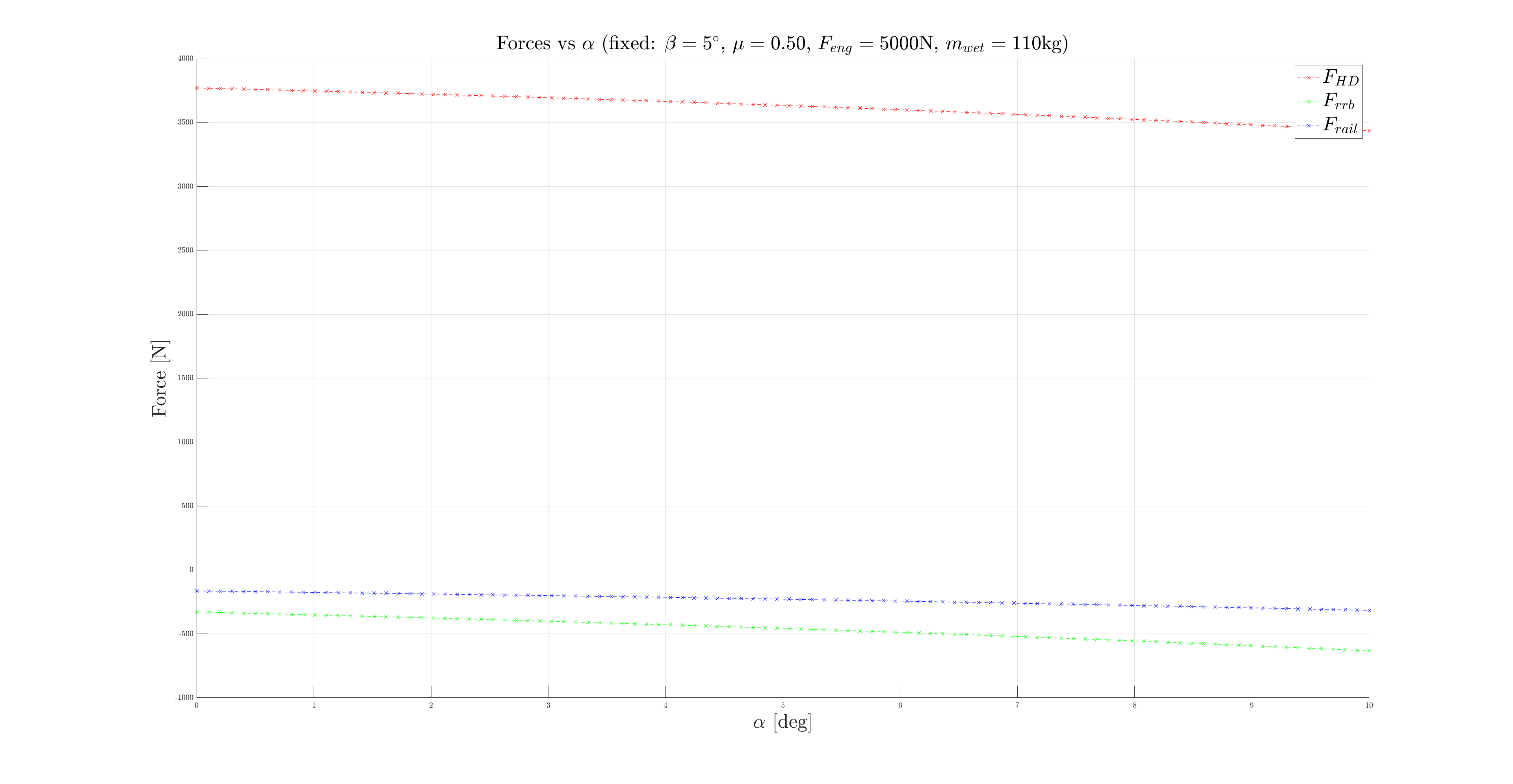
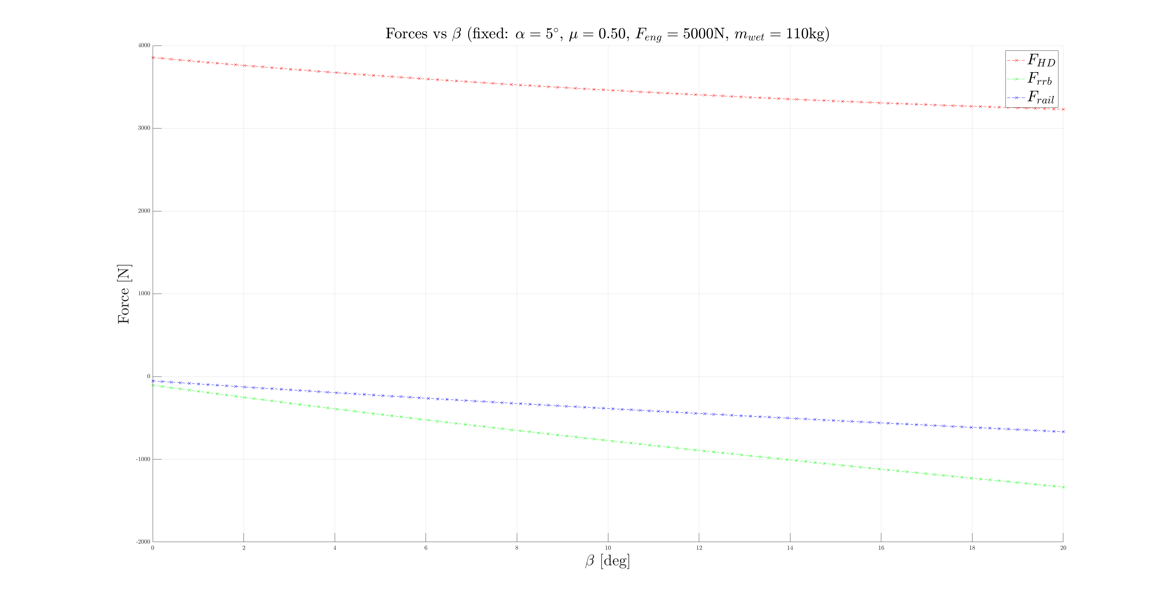
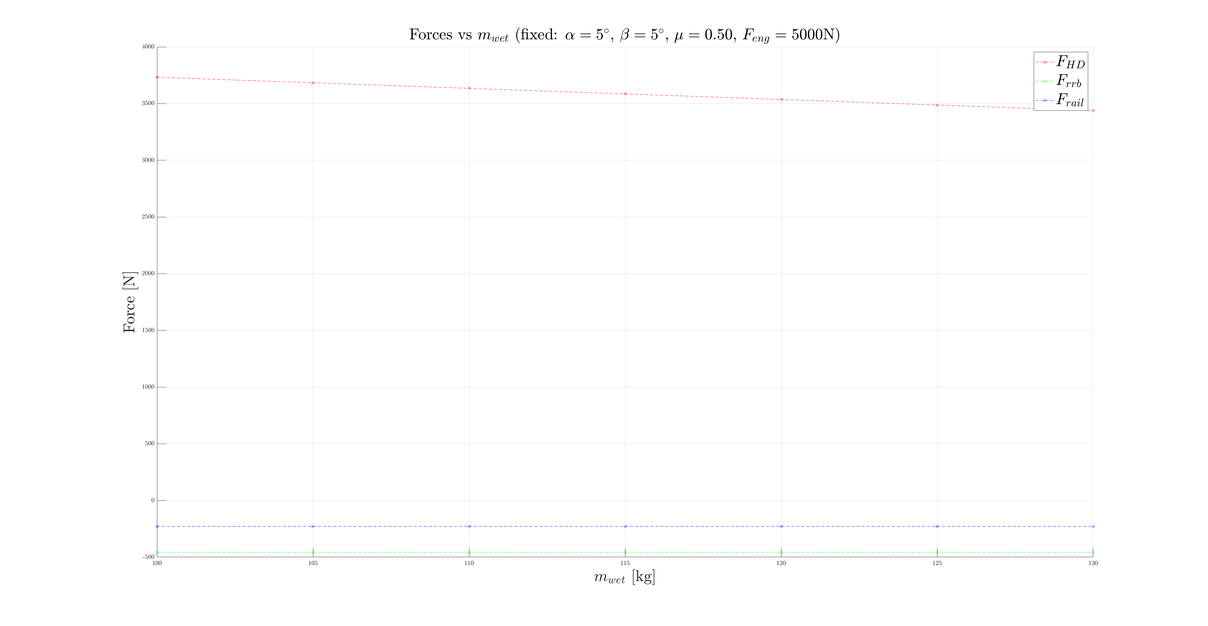
The goal is then to understand what force is appleid on the Hold-down depending on the values of the different parameters. Do this this, multiple plot are created. In each plot, one parameter is fixed, and the other are varied according to the following intervals:

The most important relation is between and . As expected, a large variation in the engine thrust leads to a large variation in the force experienced by the Hold-down pin, as can be seen below.
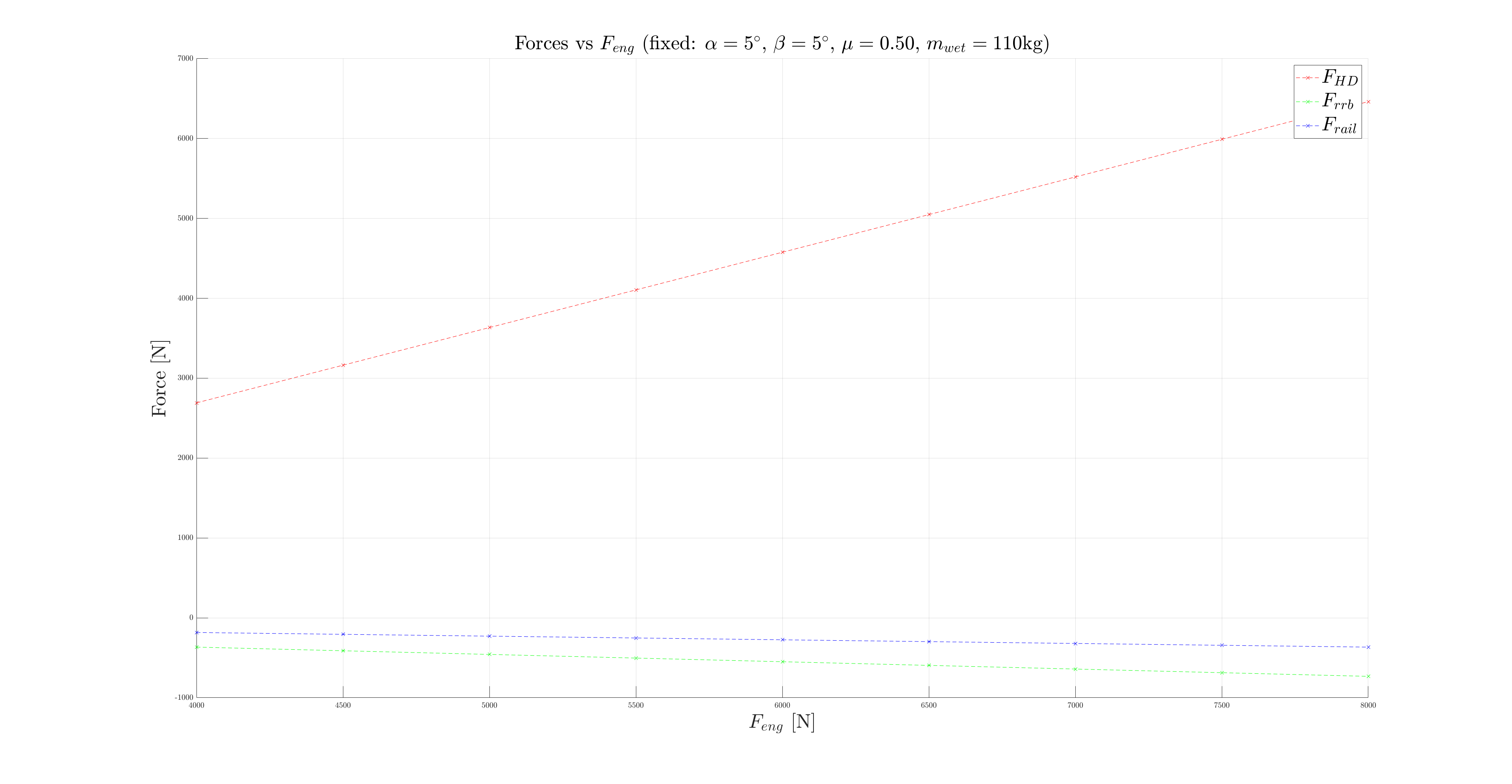
The plots corresponding to the other relations and their intervals are given below to convince the reader that the relation is the most significant one ( is highlighted in red and varies only of ~ at most when the other parameters are swept across the defined intervals).

¶ Conclusion
Based on these calculations, it was decided to select a Hold-down pin designed to break at the target force of and another one designed to break at . This choice was made after considering the sources of error and the potential variations in before the launch. This gives two options, the one where we minimize the risk of having but maximize the risk of not being able to break the pin, and the pin which is the opposite but still provides an acceptable value for .
¶ Slinging
Please refers to the following document for precise dimensioning of slinging elements
- 2025_C_ST_HOLD-DOWN_DJFSlinging hardware description