¶ Introduction
Written by
- Icarus Systems Engineer (+ PDS on Gimbal): Guillaume Hueber
- President (PDS Gimbal) : Jérémie Huser
Intended Audience
- Icarus Structure Team Leader : Ariel Du Luart
- Icarus TM & TL
The Icarus Project pursues to develop an actively controlled hopper vehicle. For achieving this objective the rocket needs to be controlled by Thrust Vector Control (TVC), a way to do that is with a gimbal mechanism. In this project, a 2 Degree of Freedom (DOF) gimbal mechanism must be designed for the bi-liquid engine DEMO-A3.
This Design Justification File will go over the state of the art and then the different mechanisms that were developped for the rocket team as members came and went to try to find a solution to the gimbal mechanism.
¶ State of the Art
Thrust vector control is a critical technology utilized in aerospace systems to maneuver and control the direction of thrust produced by engines. By dynamically altering the direction of the exhaust gases, TVC enables precise control of the vehicle’s orientation, stability, and trajectory. This capability plays a major role in various vehicles, including spacecraft, rockets, and aircraft. These systems enhance maneuverability, improve mission flexibility, and enable advanced flight control strategies. TVC mechanical systems are already extremely optimised and it seems to be difficult to improve the current designs.
Compliant mechanisms might be the key to view the problem from a different angle and change the classical approach of mechanical TVC systems.
In a basic rocket, the vector force of the rocket nozzle is colinear with the center of mass of the rocket body. This doesn’t create any torque around the center of mass. The idea behind thrust vectoring is to change the line of action of the rocket motor to control pitch and yaw. This allows to correct the rocket direction back to the desired orientation if needed. Thrust vectoring can be done in a few ways including additional “Vernier” thrusters, jet vanes or gimbaling the engine or nozzle [3]. Gimbals were chosen for this application as it’s simpler for small scale tests. Gimballing the nozzle would have been simpler from a mechanical point of view; but this complicates the construction of the motor.
¶ Definitions and Abbreviations
- TVC : Thrust Vector Control
- DOF : Degree of Freedom
¶ Relevant Knowledge Needed
5 reports on gimbals have been done since the start of the Hopper project.
- Gimbal design by Heloise Nolf Fall 2021 (focus on the actuators)
- Gimbal design by Etienne von Loë Spring 2022 (focus on the CAD)
- Choice of Maxon actuators by Theotime Lemoine Fall 2022 (new CAD, actuators calculations)
- Gimbal design by Arnaud Gauthey (HEIG) Spring 2023 (new CAD, existing actuators)
- HUEBER_HUSER_IAC_2023
¶ Design Options
¶ State of the art of compliant mechanisms
Compliant mechanisms simplify the design by reducing part counts, thus enhancing precision, reliability, and weight management, critical for aerospace applications. It eliminates the need for lubricants, increasing longevity during extended space missions (Howell, 2001).
A fully compliant space pointing mechanism has already been designed. In addition to it being compliant, its monolithic construction allows to save weight and to have an equal coefficient of thermal expansion. It also has the advantage of having two actuators that can be attached to ground, reducing rotational inertia.
A problem with this design is its relatively low support stiffness. It does sustain a thruster's load of 445 N but this system is mainly designed as a pointing mechanism on earth orbit satellites.
While the design allows plumbing and wiring to pass through the mechanism, it doesn't allow the whole rocket engine to pass through. While this keeps the structure compact, it forces the center of rotation to be on the edge of the rocket engine or nozzle thus resulting in a higher rotational inertia requiring more torque from the actuator.
Compliant high support stiffness were considered (Naves et al.). Parallel stacked folded leafsprings allow a very high support stiffness and load capacity while still having a large range of motion.
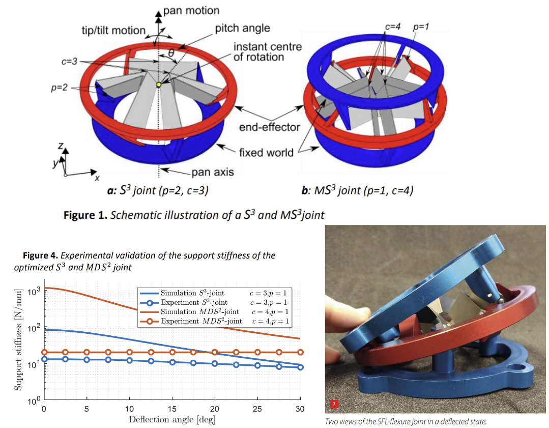
Another spherical flexure joint based on tetrahedron elements can sustain an incredible vertical load. It has the advantage to have its CR away from the structure, potentially having the CR at the CM of the rocket engine. The problem is the further away the CR is to the structure, the bigger the structure has to be. This makes it non suitable for this project.
The disadvantage of these tools is that the CR would be on the edge of the rocket engine resulting in a higher rotational inertia or the structure would be very large. They also render difficult the space for propulsion feed lines.
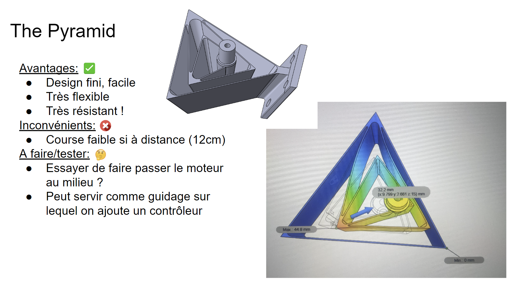
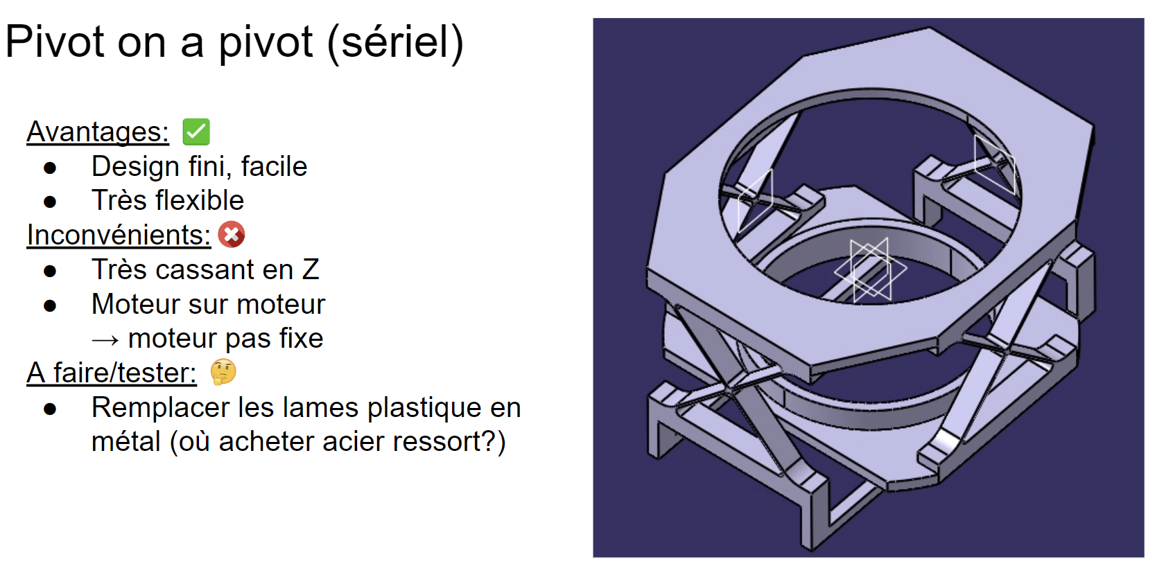
Other interesting compliant mechanisms:
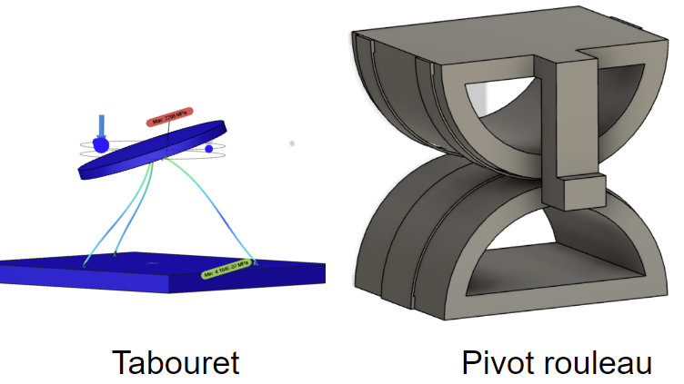
The initial idea of our mechanism :
¶ Proposed mechanism
The main gimbal structure can be summarised as two pivots in series, one pivot for each axis. These pivots are doubled on each stage to divide the vertical load on each pivot by 2.
By separating the main pivot into two, this allows the rocket engine to pass through the mechanism. The center of rotation can thus be located at the center of mass of the engine which has a much lower rotational inertia compared to having the CR at the edge of the engine.
This allows a faster response time from the two actuators without a higher torque, which is critical in TVC systems.
The fact that the engine can go through the mechanism also has the advantage of not risking damaging plumbing and wiring from pinching or shearing.
¶ Different pivots
There exist many different kinds of compliant pivots and our choice was clearly focus on having a high stiffness in the vertical axis and also on the ease of manufacturability. Flexure-based pivots which required the use of Wire-EDM were therefore avoided due to cost.
The cross-spring pivot was chosen for its simplicity, low stiffness and large range of motion. To achieve the actuator decoupling, a full cross spring pivot would work but its large size would increase the already large volume of the mechanism. The RCC pivot would allow a smaller footprint but a simple flat spring works as well and has a lower stiffness.
Pivots in compression lead to the flat springs buckling.
Pivots in traction lead to flat springs subjected to tensile stress so no buckling takes place. The pivots can therefore sustain a greater load.
This brought us to use a “traction-traction” system by adding a vertical member between the two stages. This leads to all pivots of the system being in traction, instead of a standard “traction-compression” system where one stage is in compression and the other is in traction.
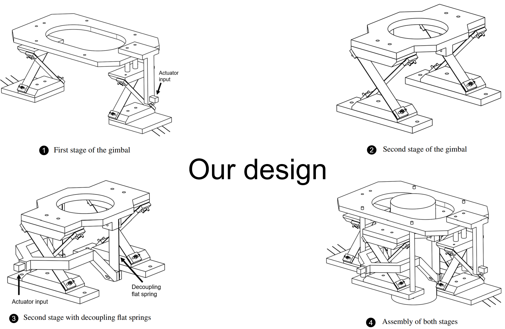
¶ Decoupling the actuation
Instead of having the second stage actuator moving with the first stage, the second stage actuator input was decoupled from the first stage. So both actuators can be connected to ground. This simplifies actuator mounting and lowers the rotational inertia of the first stage.
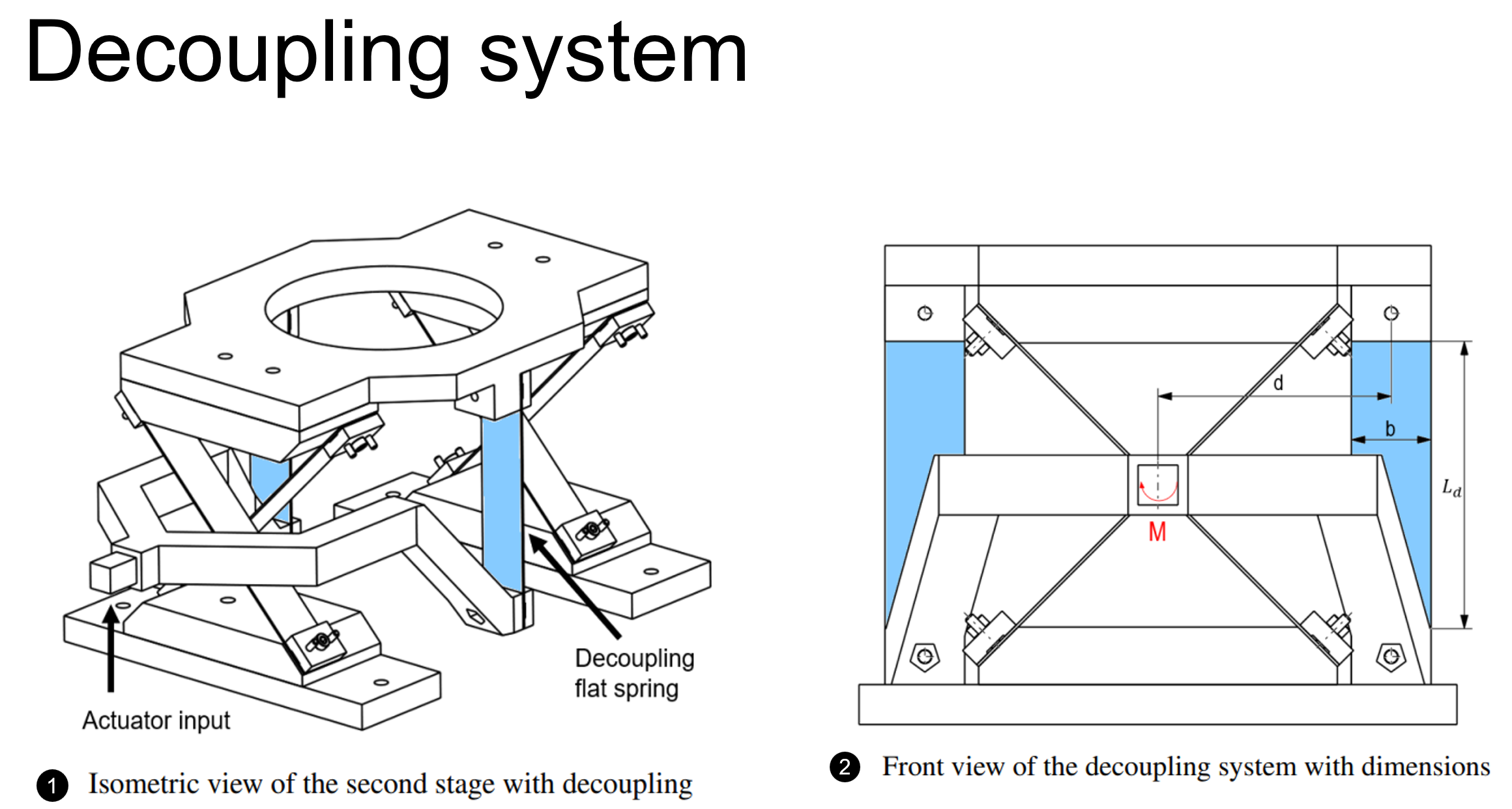
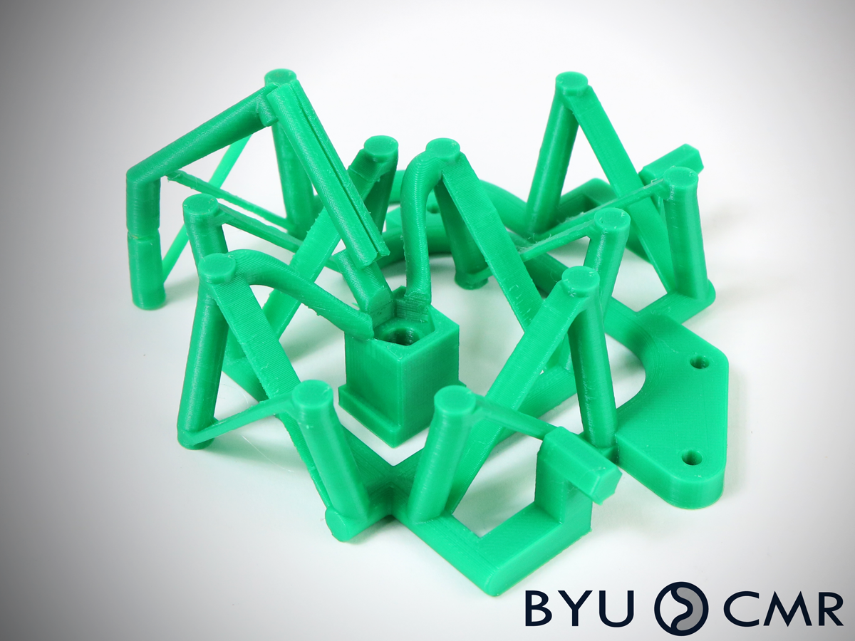
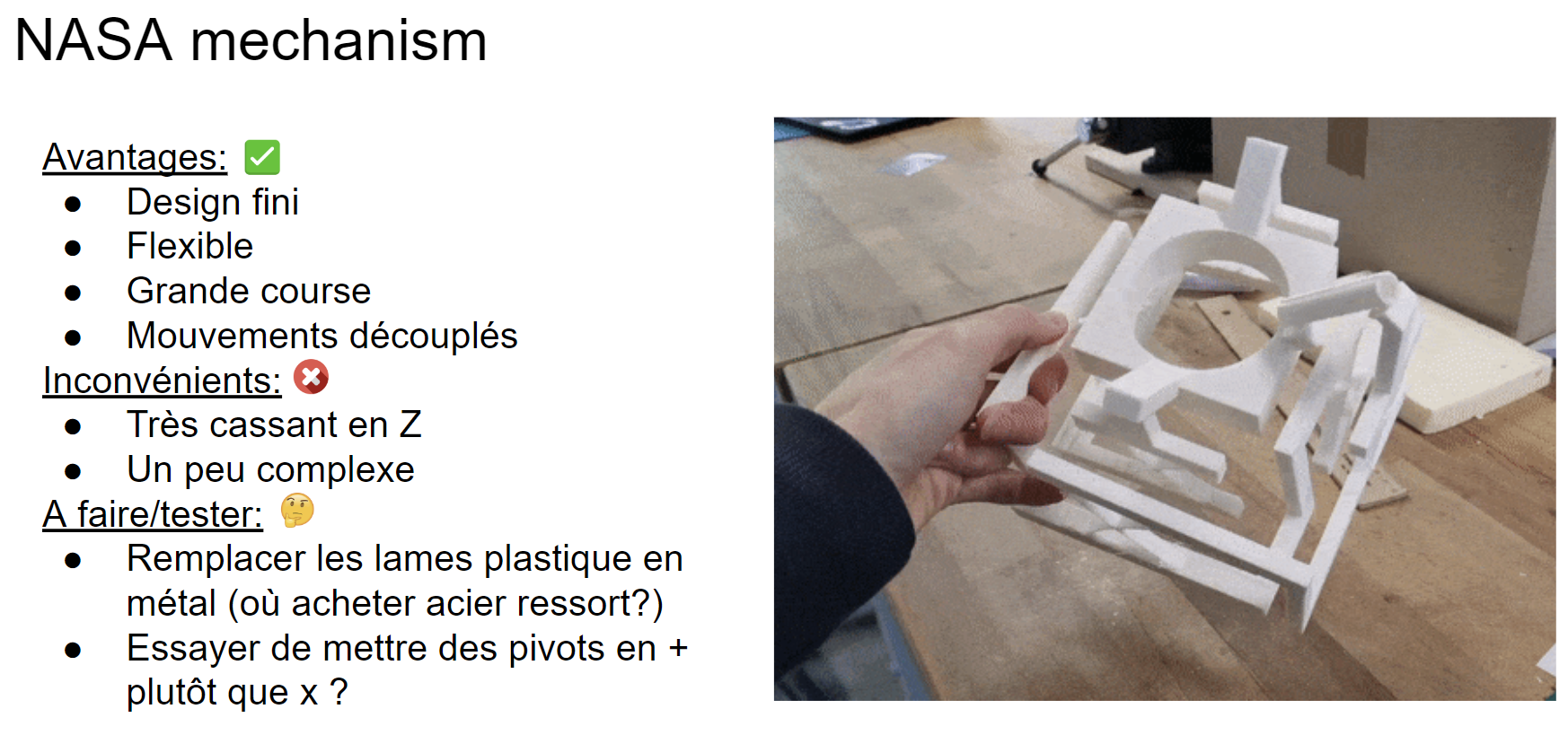
The decoupling system is very interesting for a scientific paper as its a novel way of doing this and it works as one can see with the 3D printed prototype. However, the prototype allowed us to see the problems linked to this decoupling system which we then considered to be non essential. Some problems were that:
- The decoupling flat springs would be very close to the rocket engine which would be around 500°C.
- The actuator input arm limits the range of the gimbal by adding collisions.
- The actuator input arm would be quite complex to manufacture.
- The maxon actuators that were selected for this gimbal had extra torque that could be used for moving more inertia.
This led to this design here:
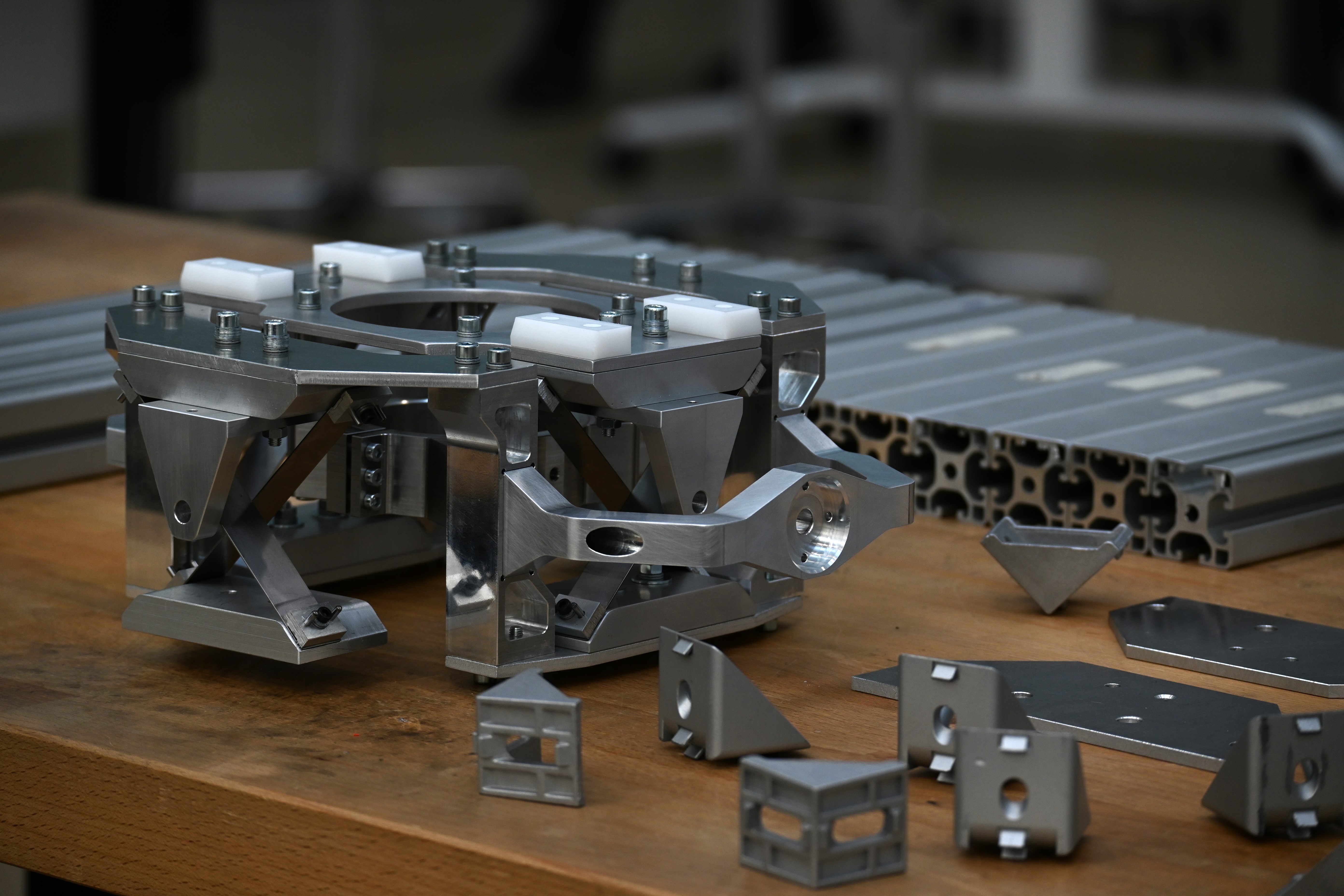
What changed is, for example, the link between the pivots on the first stage where it was done on the side rather than on the top. This is seen as the motor mount on the left of the gimbal on the image.
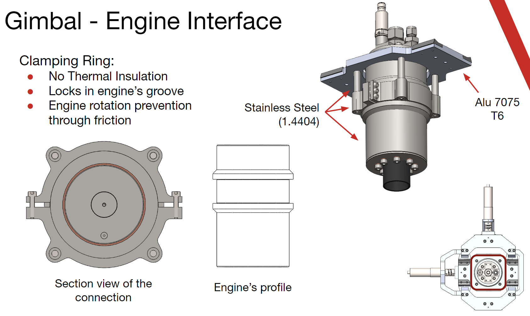
¶ Gimbal Engine Interface
What has not been discussed in this document yet is the interface with H-AC's DEMO-A3 rocket engine. This is done through a shoulder in the engine's profile to transmit the load of the engine to the gimbal.
To be able to assemble and dissassemble the engine to the gimbal, this shoulder is held with a clamping ring in two seperate parts as one can see in the picture. To prevent rotation of the rocket engine (despite being closed with 6 M4 screws) due to the vibrations from the rocket engine, there is another perpendicular pointed set screw that will block the engine's rotation.
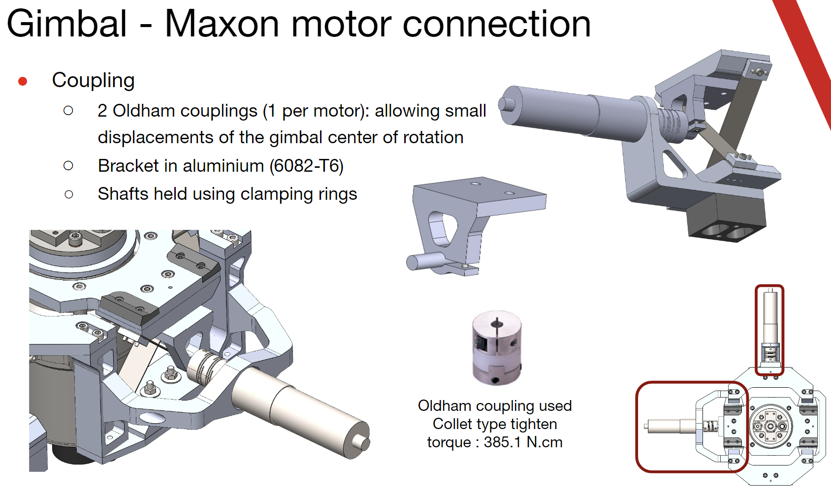
¶ Gimbal maxon couplings
We chose Oldham couplings to link the maxon motors to the pivots as the pivots have a deformation of the center of rotation when deforming.